Опис
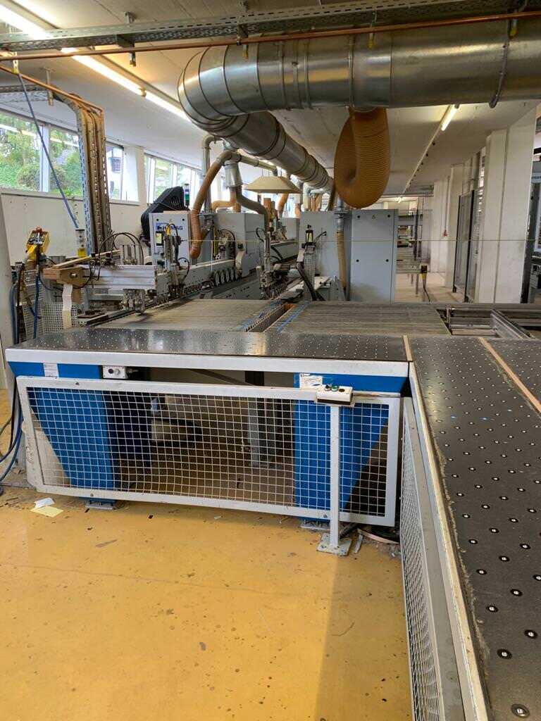
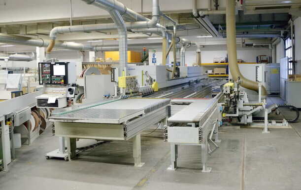
Single-sided Edge Banding and Finishing Machine
Special machine for three spine component production
Work piece specification:
Chip board, MDF, melamine coated
Dimensions:
Length: min. 250 mm, max. 3000 mm
Width: min. 250 mm, max. 3000 mm
Thickness: min. 10 mm, max. 40 mm
Capacity per shift: 3500 – 4500 pieces
Machine data:
Special machine on the basis of HOMAG
Rebuilding and modification by M&S Ziemer GmbH
KFR 23/22/08/QA/35
Double-sided HOMAG Formatting and single-sided Edge Banding Machine
Fix fence side right, movable side left
BASIC MACHINE
With continuous machine post and unit support, prepared for installation of the format processing units double-sided and edge banding and finish processing units single-sided
Glue roll drive at feed stop
Incl. basic length sound enclosure for formatting and finish working part with central exhaustion
WORK PIECE TRANSPORT DEVICE
Continuous chain belts
Rolling block link chain with ball bearings at running and guiding surfaces
With precise hardened running and guiding surfaces
Magnetic motor brake of transport chain
Feed drive frequency controlled, speed adjustment at input unit
TOP PRESSURE
With driven, continuous V-belts
Motor-driven height adjustment by cardan drive with digital positioning display
WIDTH ADJUSTMENT OF THE MOVEABLE SIDE
Linear guidance as well as rolling guidances on hardened supports
Motorized fast and crawl motion drive
Ball spindles and cardan drives for precise positioning
Digital positioning display
FINISH PAINT
Structure lacquer grey RDS 240 80 05
ELECTRICAL EQUIPMENT
It is absolutely necessary to state the voltage (basis 380 V/50 cycles)
Operating voltage 400 V, 50 cycles
Control voltage 230 V, 50 cycles
Installed acc. Euronorm EN 60204
Hand switch for setting mode
Cooling unit in control cabinet
Control cabinet separate
Connecting cable to machine as per installation plan
SIEMENS ELECTRONIC CONTROL
PLC - programmable logic controller with LED display of all inputs and outputs
Integrated line control for touch-less control of the processing units
Multi-task control of the PLS for precise unit operations
Variable number of pieces in the machine
Compatible serial interface to all
Prescribed ambient temperature +5 degrees - + 35 degrees C
CONTROL
SIEMENS control system with graphic surface for easy and convenient operating and programming
HARD WARE
Industrial PC 68040 with 16 MByte RAM
1 PCMCIA hard disk 170 MByte
1 free PCMCIA input module for data backup
Colour display 12,1” with PC compatible keyboard integrated in operating desk at infeed
Extendable with net plug Ethernet
SOFT WARE
Operation with Windows standard by menu
Menu-guided generation of working programmes
Production according working programmes
PLC diagnosis in contact diagram method at monitor
Remote diagnosis:
Internet access of the machine, tele-service by electrician of M&S Ziemer GmbH
SAFETY AND PROTECTION DEVICES
All machines or EU member states with CE mark as per EG machinery rules 89/392/EWG annex IIA
Wood dust tested TRK value max. 2 mg/m³ if the suction output at site as per plan is complied.
Documentation in 2-fold
TECHNCIAL DATA
Feed infinitely variable 10-40 m/min.
Work piece excess length 40 mm
Work piece thickness 8 – 60 mm
Working height up to upper chain edge 950 mm
Working width double-sided min. 240 – 270 mm
(depending on machine equipment)
Working width double-sided max. 3500 mm
Pneumatics 7-8 bar
Technical specifications for the basic machine can vary according to the processing units.
Ground conditions must correspond with the foundation plan
Number: 0013 1 x right
INFINITELY VARIABLE AXIS FOR INFEED FENCE
For lateral adjustment to different work piece excess lengths
Number: 0029 1 x right
INFEED DEVICE 4 ROLLS FOLDING UPWARDS
With inclined driven rolls
Min. work piece length 250 mm
Number: 0033 1 x right
ELECTRO-PNEUMATIC FOLDING UPWARDS
Of the infeed device and can counter holding device, programme-dependent controlled
Number: 0067 1 x left 1 x right
CHAIN TRACK EXTENSION MACHINE II + 1000 mm
For placing the pieces in front of the fence cams incl. 2. aligning station
Number: 0070 1 x left 1 x right
ALIGNING STATION
For lateral fixing of the work pieces
Number: 0072 1 x left 1 x right
INFINTELY VARIABLE AXIS FOR ALIGNING STATION
For lateral adjustment of the aligning station
On the movable machine side at automatic work piece excess change
Number: 0900 1 x
LAMINATED WOOD SUPPORT PNEUMATICALLY LOWERABLE
Required at automatic longitudinal/cross thru feed in direction with M II + 500/1000
For example in a short line
Number: 0211 28 x right
FENCE CAMS INFINITELY VARIABLE
Cam distance max. 25 mm each
Number: 0212 1 x right
INFINITELY VARIABLE FENCE CAMS MANUAL
Cam distance 25 mm, manual
Adjustable to 4 different heights
Electro-pneumatic control for moving out the cams
Pre-selection of the cam distance
Number: 0308 2 x right
LATERAL ADJUSTMENT UNIT SUPPORT INFINITELY
For automatic change of the work piece excess length in the range of 30-80 mm
Number: 0650 2 x
WORK PIECE SUPPORT FOR SINGLE-SIDED MACHINE
Basic design KFL/R 10, additionally for the work piece support equipped as standard
NOTE:
Additionally for standard equipment
Number: 0652 30 x
EXTENSION OF THE WORK PIECE SUPPORT
Per increment
Number: 0654 1 x
EXTENDIBILITY OF THE WORK PIECE SUPPORT
to max. 1500 mm, incl. ground supports
MODIFICATION
To max. 2500 mm
Number: 0871 1 x
CAM LOWERING FOR DIVIDED BASIC MACHINES
For automatic lowering and moving out of the cam fence
Cam distance max. 25 mm
Manual adjustable to 4 different heights
Pre-selection of the cam distance
NOTE:
For left machine side
Number: 1005 1 x left 1 x right
MILLING POST 1 GUIDANCE
Number: 1317 1 x left 1 x right
STANDARD MILLING UNIT PNEUMATIC CONTROL 6,6 kW
1 Milling motor 6,6 kW, 100 cycles, 6000 rpm
Cross support, reversing switch turning direction
Suction hood, intermediate support with round guidance
Electro-pneumatic control for jumping
Tilting range 90 degrees
Tool diameter max. 200 mm
Without tools
Incl. electronic frequency converter with
Motor brake function and extension noise protection
For the use of grooving or rebating in parallel direction, Number 1262 is additionally required.
NOTE:
For scoring and vertical control
Number: 1531 1 x left 1 x right
INFINITELY VARIABLE AXIS HORIZONTAL
For positioning of the processing units
Key-switch for motor locking
Number: 1551 1 x left 1 x right
INFINITELY VARIABLE AXIS VERTICAL
For positioning of the processing units
Key-switch for motor locking
Number: 1554 1 x left 1 x right
INFINITELY VARIABLE AXIS SWIVELLING
Number: 1210 1 x left 1 x right
HOGGING UNIT 8,1 kW
1 motor 8,1 kW, 100 cycles, 6000 rpm
Supporting surface for scoring motor
Cross support, double suction hood
15 degrees tilting at 60 mm work piece excess
Activation of star-delta
Tool diameter max. 250 mm
Without tools
Incl. electronic frequency converter with motor brake function and extension noise protection
Number: 1607 1 x left 1 x right
MOTOR SPINDLE D=40 FOR SUPPORT OF HYDRO SLEEVE CLAMPING
Special motor spindle dimensions without norm wedge
Motor spindle 75 mm long, hardened
Number: 1531 1 x left 1 x right
INFINITELY VARIABLE AXIS HORIZONTAL
For positioning of the processing units
Key-switch for motor locking
Number: 1551 1 x left 1 x right
INFINITELY VARIABLE AXIS VERTICAL
For positioning of the processing units
Key-switch for motor locking
Number: 1554 1 x left 1 x right
INFINITELY VARIABLE AXIS TILTING
Number: 1010 1 x left 1 x right
MILLING POST 2 GUIDANCES
Number: 1332 1 x left 1 x right
COMPACT CHANGE MILLING UNIT KW 12,2 x 4,5 KW
2 motors each 4,5 kW, 100 cycles, 6000 rpm
Cross support, electro-pneumatic control for both motors,
Start stroke max. 15 mm
Tilting range 90 degrees, manual by spindle
Suction hood for both motors
Tool diameter max. 180 mm
Without tools
Incl. electronic frequency converter with motor brake function and extension of noise protection
Number: 1531 1 x left 1 x right
INFINITELY VARIABLE AXIS HORIZONTAL
For positioning of the processing units
Key-switch for motor locking
Number: 1551 1 x left 1 x right
INFINITELY VARIABLE AXIS VERTICAL
For positioning of the processing units
Key-switch for motor locking
Number: 1554 1 x left 1 x right
INFINITELY VARIABLE AXIS TILTING
Number: 0445 1 x left 1 x right
SEPARATING WALL FOR NOISE PROTECTION FORMATTING PART
Number: 1305 1 x left 1 x right
STANDARD milling unit 4,5 KW
1 milling motor 4,5 kW, 100 cycles, 6000 rpm
Cross support, reversing switch for turning direction,
Suction hood, tilting range 180 degrees
Tool diameter max. 200 mm
Without tools
Incl. electronic frequency converter with motor brake function and extension noise protection
MODIFICATION
With supporting rolls
Number: 1531 1 x left 1 x right
INFINITELY VARIABLE AXIS HORIZONTAL
For positioning of the processing units
Key-switch for motor locking
Number: 1551 1 x left 1 x right
INFINITELY VARIABLE AXIS VERTICAL
For positioning of the processing units
Key-switch for motor locking
Number: 1554 1 left 1 x right
INFINITELY VARIABLE AXIS TILTING
Number: 1605 1 x left 1 x right
EXTENDED MOTOR SHAFT 120 MM LONG
With activation star-delta
Number: 1010 1 x left 1 x right
MILLING POST 2 GUIDANCES
Number: 1305 1 x left 1 x right
STANDARD MILLING UNIT 4,5 KW
1 milling motor 4,5 kW, 100 cycles, 6000 rpm
Cross support, reversing switch turning direction,
Suction hood, tilting range 180 degrees
Tool diameter max. 200 mm
Without tools
Incl. electronic frequency converter with motor brake function
And extension noise protection
Number: 1531 1 x left 1 x right
INFINITELY VARIABLE AXIS HORIZONTAL
For positioning of the processing units
Key-switch for motor locking
Number: 1551 1 x left 1 x right
INFINITELY VARIABLE AXIS VERTICAL
For positioning of the processing units
Key-switch for motor-locking
Number: 1605 1 x left 1 x right
EXTENDED MOTOR SHAFT 120 MM LONG
With activation star delta
Number: 2011 1 x right
COMPACT GLUING PART A3
For straight edges, consisting of:
Hot Melt Gluing Unit QA 34
Melting unit with granulate container
Temperature control electronically with LED-display
Glue roll drive at feed stop
Glue roll lift at feed stop
Glue container clamping operated by work piece
Magazine – 2 Rolls
Edge Thickness 0,3 – 3,0 mm
Edge Width 12 – 65 mm
Roll diameter 830 mm
Processing max. – at PVC 135 mm²
-at veneer 100 mm²
Roll separating device
Roll change automatically or manually
Edge monitoring with feed stop
Residual length monitoring at 2400 mm
Magazine height adjustment via spindle
Adjustment way +/- 5 mm
Pressure Zone K
1 driven pre-pressing roll diameter 150 mm
2 finish pressing rolls diameter 70 mm
Number: 2457 1 x right
EXTENSION MAGAZINE A3 TO 6 ROLLS
Instead of 2-fold roll
Edge thickness 2 x 3 mm und 4 x 1 mm
Roll diameter 2 x 830 mm and 4 x 600 mm
Roll change automatically or manually
Residual length monitoring at 2400 mm
Number: 2472 1 x right
EDGE DOWN-HOLDER INFINITELY VARIABLE
For automatic adjustment to different edge heights
Number: 2603 1 x right
INFINITELY VARIABLE AXIS HORIZONTAL PRESSURE ZONE C/G/GL
For automatic lateral adjustment of pre-press and finish press rolls via infinitely variable axis
Number: 3047 1 x right
END TRIMMING UNIT HL 81 CHAMFER/STRAIGHT
2 motors each 0,18 kW, 200 cycles, 12000 rpm
Edge thickness straight max. 6 mm
Chamfer max. 3 mm
Edge width max. 65
Edge cross section max. 270 mm²
2 HM special end trimming saws diameter 120 mm
Autom. central lubrication of the linear guidances
Incl. electric frequency converter with motor brake function
And extension of noise protection
When the top coating is overlapping, there’s no end trimming possible.
ALTERATION
For work piece thickness min. 8 mm
Number: 3117 1 x right
AUTOMATIC ADJUSTMENT HL 81/83
For electro-pneumatic modification from chamfer to straight and infinitely variable adjustment
of the lateral end trimming fence for chamfer trimming at different edge thicknesses.
Number: 3203 1 x right
PRE-MILLING UNIT TOP AND BOTTOM 0,55 KW
2 motors on top of each other
Each 0,55 kW, 200 cycles, 12000 rpm
Manually lateral movable
Motors with plug-connection
Height adjustment by top pressure
Counter working
Edge thickness max. 6 mm
Work piece thickness 7 – 60 mm
Tilting range +/- 1 degree
2 HM cutter 70 x 25 mm, HSK 25, Z=4
Incl. electronic frequency converter with motor brake function and extension noise protection
Number: 1305 1 x right
STANDARD MILLING UNIT 4,5 KW
1 milling motor 4,5 kW, 100 cycles, 6000 rpm
Cross support, reversing switch turning direction,
Suction hood, tilting range 180 degrees
Tool diameter max. 200 mm
Without tools
Incl. electronic frequency converter with motor brake function and extension noise protection
Intermediate sliding carriage – 1 x right
Pneum. out stroke
Number: 1005 1 x right
Milling post 1 guidance
Number: 1305 1 x right
STANDARD MILLING UNIT 4,5 kW
1 milling motor 4,5 kW, 100 cycles, 6000 rpm
Cross support, reversing switch turning direction
Suction hood, tilting range 180 degrees
Tool diameter max. 200 mm
Without tools
Incl. electronic frequency converter with motor brake function and extension noise protection
Number: 1531 1 x right
INFINITELY VARIABLE AXIS HORIZONTAL
For positioning of the processing units
Key-switch for motor locking
Number: 1551 1 x right
INFINITELY AXIS VERTICAL
For positioning of the processing units
Key-switch for motor locking
Number: 1554 1 x right
INFINITELY VARIABLE AXIS TILTING
Number: 1605 1 x right
SUCTION HOOD FOR PARALLEL WORKING
For better chip removal during grooving/milling
In parallel run incl. extension noise protection
Milling motor attached at rear post side
Number: 4501 1 x right
FINISH CLEANING DEVICE GLUE JOINT
Removal of residual glue in the joint glue area. Scanning from top and bottom.
Height adjustment with the top pressure with carbide-tipped knife
Blowing nozzles electro-pneumatically controlled
Unit top and bottom max. 50 mm laterally movable
Number: 4520 2 x right
ADJUSTMENT DEVICE PNEUMATICAL
For electro-pneumatic lateral moving out of the working area
Number: 4402 1 x right
BUFFING UNIT TOP AND BOTTOM WITH OSCILLATION
To make the edges grip
2 motors each 0,25 kW
Inclined and height adjustable
Height adjustment with the top pressure
Oscillation device for using the disc width for upper and lower motor
2 Molton discs diameter 150 x 50 x 25 mm
1 x right
Free space approx. 1000 mm
For 5-G-unit
REBUILT MACHINE WITH NEW MACHINE GUARANTEE
Design acc. CE regulations
Machine dimensions:
Length 14200 mm
Width 7400 mm
Required space of complete line:
Length 14200 mm
Width 9400 mm
Total suction capacity: 27000 m³/h
Air speed: 35 m/s
Compressed air consumption: approx. 1300 NL/min.
Total connected load: approx. 100 kW
Nominal voltage: approx. 160 A
WITHOUT processing tools and tool holders.